or simply scroll down yourself.
Synthetic Aperture Radar or SAR is an electromagnetic imaging sensor often used in remote sensing applications. The SAR sensor is mounted on an aircraft or a satellite, and is used to make a high-resolution image of the earth's surface. Occasionally it is used for more remote applications, such as making an image of the surface of Venus (see Magellan Mission).
The other main sensor used to image the earth is an optical sensor like a film camera or a TV camera. While the optical sensors also record electromagnetic energy, there are three main differences between SAR and an optical sensor. Firstly, they use different frequencies or wavelengths. SAR uses a wavelength of 1 cm to 1 m, while optical sensors use wavelengths near that of visible light, or 1 micron. This difference in wavelengths means that SAR can be used to see through clouds and storms, while optical sensors can not. It also means that objects on the earth's surface look quite different in the two sensors, because the scattering or reflection mechanisms of electromagnetic waves are quite dependent upon frequency or wavelength. Objects which look smooth at one wavelength may appear quite rough at a shorter wavelength, and surface roughness often determines the strength of the received signal.
Secondly, optical sensors rely upon the sun's illumination or thermal radiation to create the brightness that is observed by the sensor. In contrast, a SAR sensor carries its own illumination source, in the form of radio waves transmitted by an antenna. This means that the optical sensor's image depends upon the time of day (because of the varying sun angle), while SAR can be used with equal effectiveness at any time of the day and night.
Thirdly, SAR is a side-looking sensor, while optical sensors mainly look straight down. Also, SAR sensors portray angles to an object differently because SAR measures range rather than angle in the direction perpendicular to the line of flight.
Effects such as these means that a SAR image usually looks quite different from an optical image of the same area. We are generally quite used to seeing how earth features appear in an optical image (although maybe not when taken from so far away in space). In contrast, SAR images often appear in an unfamiliar form, and we are still learning how to make full use of the information in a SAR image.
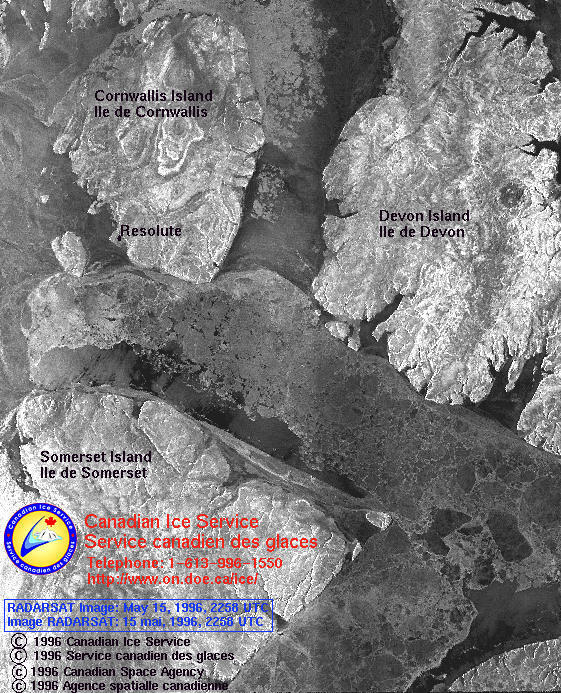
Having said the above, we cannot say that a SAR image is better than an optical image, or vice versa. They contain different information, and for some applications SAR images are better, while for other applications, optical images are better. For example, SAR is better for imaging the ice in the Canadian Arctic. In an optical image, snow and ice appear bright white, and relatively featureless. But in a SAR image, the surface roughness patterns are clearly portrayed, and trained observers can deduce the age and thickness of the ice. The Canadian Ice Service of the Department of the Environment makes daily maps of the Arctic ice, and sends them to icebreakers to allow them to plan their routes. These maps are made from Radarsat images, such as this one of the approaches to Resolute.
The radar system generates a high-bandwidth signal or pulse, usually in the form of a chirp so that all frequencies in the range of interest are covered. Remote sensing systems generally use a bandwidth of 10 - 30 MHz, but military systems can have bandwidths over 500 MHz. The start time and the phase of the signal are precisely controlled by a stable local oscillator. The chirp signal has a duration of 10 - 40 ms, and is repeated every millisecond or so.
A power amplifier raises the signal level to 10 Kw or so, using a phase coherent amplifier such as a traveling wave tube. This signal is fed to the transmitting antenna via coaxial cable or waveguide. Sometimes the amplifiers consist of many small elements, which are located directly on the antenna patches. In other cases such as Radarsat, phase shifters are included in the distribution network, so that the pointing direction can be adjusted.
The antenna is usually a planar array, which has its longest axis along the flight direction. SAR systems generally have very long antennas; one of the longest one is on Radarsat, at 15 m. The length is needed to achieve high gain and to control the bandwidth of the received signal. The signal travels through the atmosphere to the ground at the speed of light (300 m per microsecond), and is scattered by the earth's surface. A portion of the radar energy scattered back along the direction of the radar beam, and is eventually received by the same antenna.
The received signal is only a few microwatts or less, and is fed to a sensitive amplifier to be raised to the milliwatt level. A routing and protection circuit ensures that the strong transmitted signal does not damage the sensitive amplifier. The signal is then demodulated down to a low intermediate frequency or to baseband, where it is sampled and stored in memory or on a tape recorder. The demodulation is done with precise timing, so that the phase of the received signal is an accurate representation of the travel time (distance) that the signal took in going from the transmitting antenna to the (same) receiving antenna. Sometimes the signal is transmitted directly to the ground using a communication downlink, but it also can be downlinked later from the tape recorders.
What is described above could apply to most coherent radar systems. What distinguishes a SAR system from an ordinary radar system is the signal processing. First of all, the demodulated received signal is compressed from 40 microseconds to a few nanoseconds using a digital matched filter or correlator. This achieves a high resolution in range of about 5 - 20 m. Most radar systems do this, but here comes the interesting part. In SAR systems, the signal can also be compressed in the azimuth direction, which is the direction of the sensor's line of flight.
An antenna, even one as long as 15m, illuminates a patch on the ground which is in the order of kilometers long. In a normal radar system, this length would constitute the radar's resolution in the azimuth direction. Such a long resolution would not be useful in remote sensing applications. But the resolution can be greatly improved using synthetic aperture processing principles as follows.
When you examine the pulse repetition frequency (1100 Hz), the sensor velocity (7000 m/s) and the beam footprint (3 Km - Radarsat parameters are given here), you see that a point on the ground is actually illuminated by 500 or so consecutive pulses. This means that information on a target is contained in 500 received pulses, and it also means that information on 500 adjacent targets or scattering points is contained in each individual pulse. If this jumbled information can be sorted out, we would have a high resolution image. How is this done ?
Considering a single scatterer on the ground, it is noted that the exact distance or range from the antenna to the scatterer will be different for every received pulse. The change in range from pulse to pulse may only be a few millimeters, but that is enough to give the signal received from the scatterer a different phase at each pulse. This change in phase is analogous to the Doppler effect, such as observed when a signal (e.g. a train whistle) from a moving (stationary) object is observed from a stationary (moving) point. The form of the phase change is different for each scatterer, so that a digital matched filter can process 500 consecutive pulses and separate them into 500 distinct scatterers.
Processing the 500 pulses or samples is analogous to how the signals from a 500-point phased array antenna would be processed in order to focus the beam to a fine point. The 500 points in this case are called the aperture of the antenna, so when the analogy is applied to the SAR processing situation, the term "synthetic aperture radar" is appropriate. The word synthetic is appropriate because the aperture is formed artificially in the signal processor, rather than being a physical antenna 500 points (3 Km) long.
The synthetic aperture processing or azimuth matched filtering is done with a 500-point correlation operation. This requires a very powerful computer, for if the range and azimuth processing were to be done in real time for Radarsat, the signal processor would have to operate at 4000 million operations per second. While signal processors have been built at this speed, it is more common for processors to operate at one tenth this speed. This is satisfactory, as SAR systems often operate for only one tenth of the time.
The algorithms for processing the SAR image are quite complicated, and have been gradually refined over the last 20 years to achieve sharper focus and faster speeds. Further improvement in the algorithms, and developing new algorithms for processing special SAR modes such as a scanning beam SAR (e.g. Radarsat) or a squinted beam SAR, is one of the main activities of UBC's Radar Remote Sensing Group.
In addition, the group performs research on a variety of SAR remote sensing technologies and applications. Of these new technologies, the most interesting are interferometry to measure the height or motion of the earth's surface, and polarimetry to recognize specific features in the SAR image. Further information on these group research topics can be found on the Research Aims page.
Here are some interesting WWW sites
about Radar Remote Sensing. Two of the most interesting sites to learn more
about SAR systems are CCRS and JPL.
See
Tony Freeman's article for another introduction to imaging radar.
 Back to RRSG
Home Page ----- ----- Return to top of this
page.
Back to RRSG
Home Page ----- ----- Return to top of this
page.